High Power Waveguide Impedance Measurement System (HiPoM)
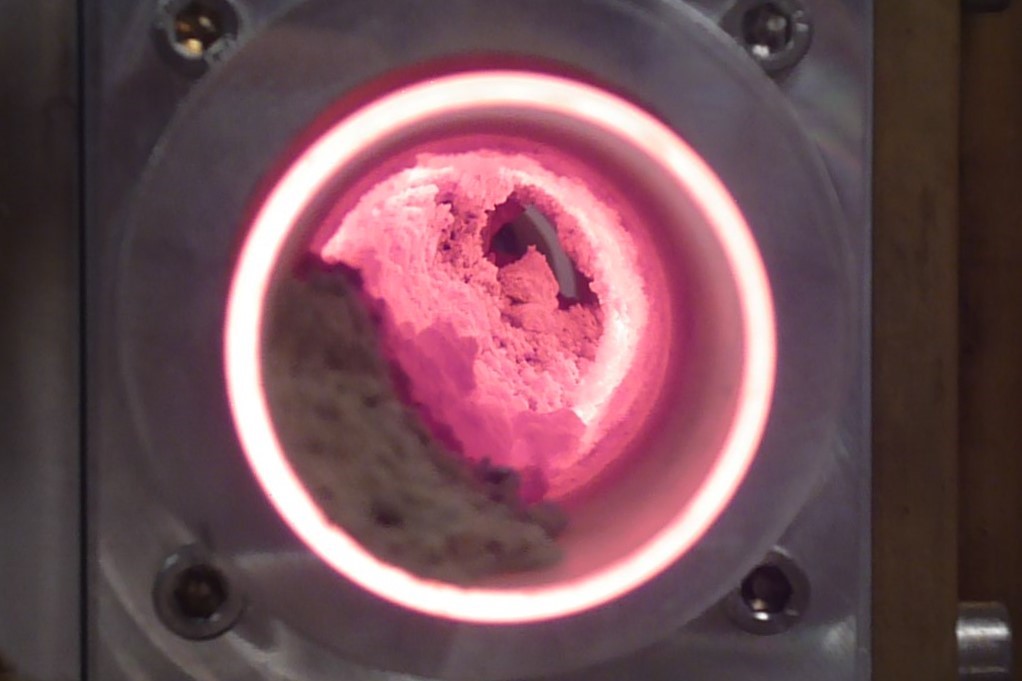
Microwave processing is a dynamic process where the properties of the processed workload change with time. Microwave parameters as dielectric properties, reflection, power balance, impedance, and frequency, etc. also experiment changes during the application of high-power microwaves.
On-line measurements of these microwave parameters can offer unique control capabilities, which might be critical for the successful application of microwave processing. Microwave industrial processes require specifically designed equipment to be used according to industrial conditions: high power, simple, affordable and robustness, while retaining a useful subset of their current functionality.
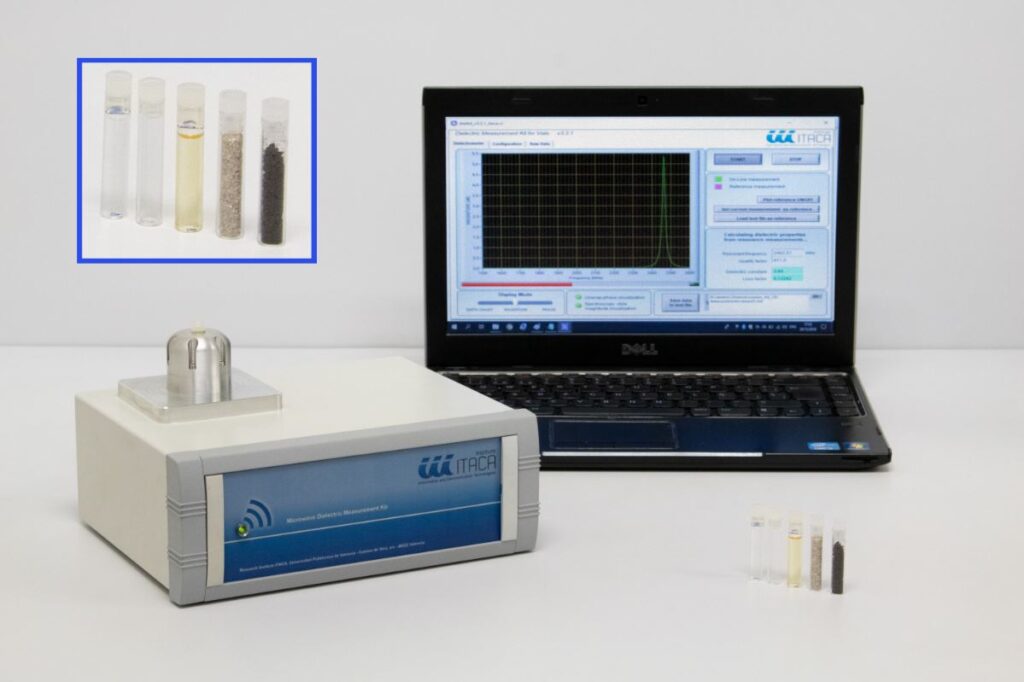
The HiPoM is a High-Power Vector Waveguide Reflectometer (1-port Network Analyzer) able to measure in real time the magnitude and phase of the impedance or the reflection (S11) at microwave frequencies (915 MHz , 2.45 GHz or 5.8 GHz) during the application of high power microwaves. Additionally, the HiPoM measures the frequency of the microwave source (magnetron or solid state) and the absolute incident, reflected and absorbed microwave power.
Typical applications include the tuning or adjusting a microwave applicator and also the monitoring of the evolution of a microwave heating process.


Figure 1. Picture of waveguide high power Vector Reflectometer around 2.45 GHz and 915 MHz.
Operation Principle
The HiPoM is based on the AD8302 integrated RF IC detector from Analog Devices. Due to the dual Matched Logarithmic Amplifiers with Phase Detector in the IC, the HiPoM presents a dynamic range of 45 dB and a high stability with temperature (-25ºC to 50ºC). The device can be used from low frequencies 0.1 to 2.7GHz.
Forward and reflected waves are separated by loop-type directional couplers with around 30-35 dB of directivity and very low coupling factors (from -40dB to -80dB) in order to accommodate the signals within the working range of detectors.
HiPoM also includes a frequency counter to measure the frequency of the source (i.e. magnetron) designed from a pre scaling divider circuit.
Calibration of the HiPoM includes the linearization of the logarithmic detectors and as any other network analyzer, directivity, port match, and tracking errors at each port of the HiPoM are corrected by a three-error term model determined by measuring three known reference standards (i.e. open, short and dummy load).
Output voltage signals from the detectors are digitalized in a multichannel analog to digital converter and processed in a microprocessor connected with a USB link to a personal computer where all the procedures are automatically performed.
Uncertainties of 0.1/0.2 dB in magnitude and 1-2º in phase respect to commercial VNA (commercial VNA measurements at low power) can be achieved with this high-power configuration.
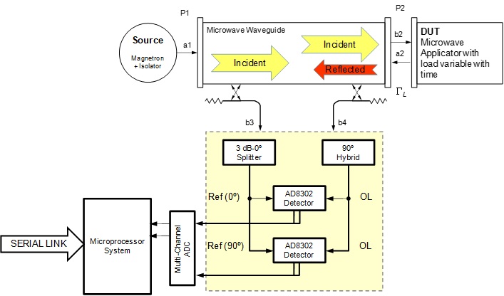
Figure 2. Schematic block diagram of the High Power Waveguide Reflectometer
Control Software
The HiPoM is driven from a PC which is connected trough a RS-232 serial cable.
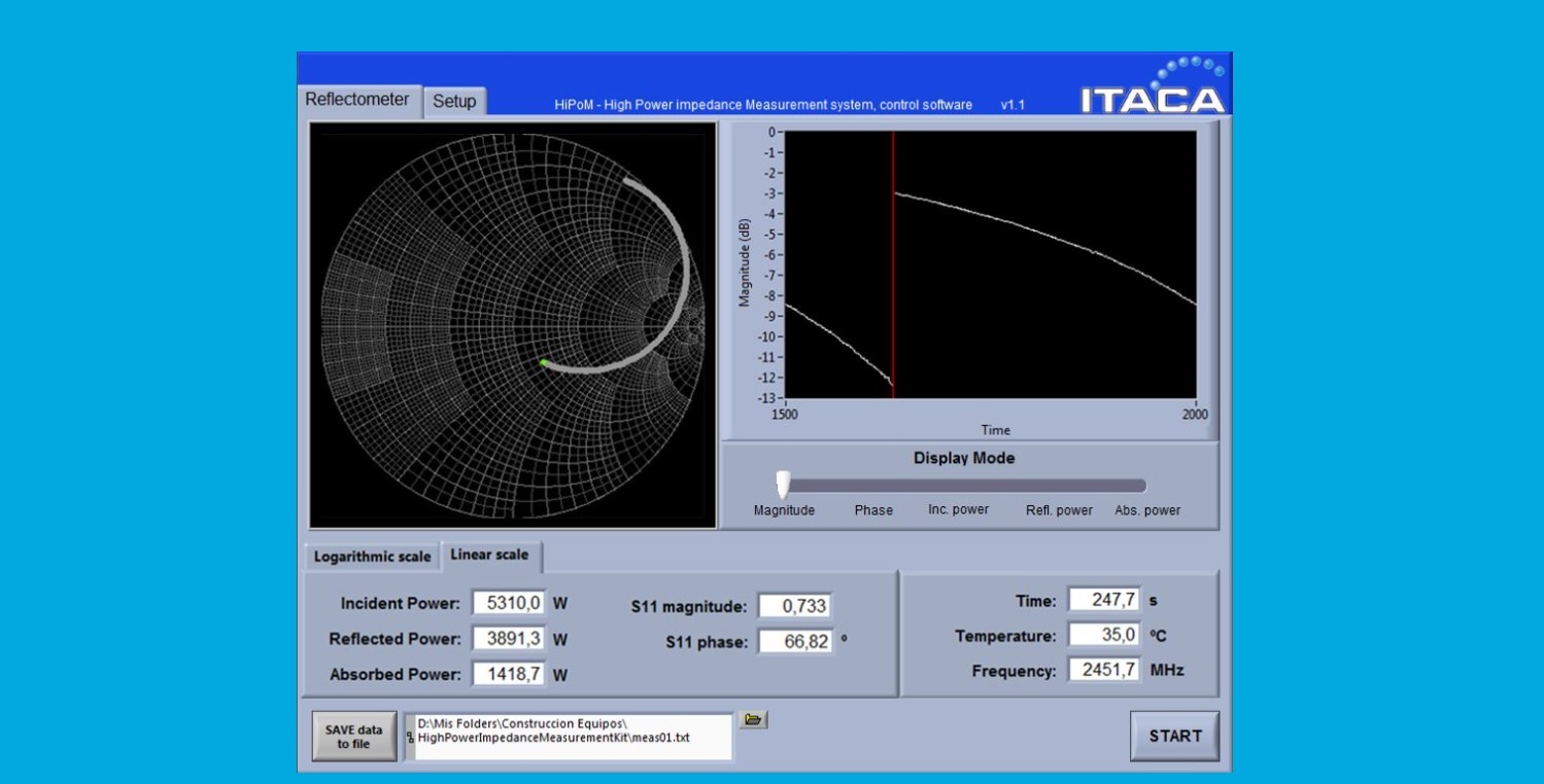
The control software permits the automatic measurement of: frequency, incident, reflected and absorbed power, module and phase of the reflection coefficient and impedance. Representation modes include: linear, logarithmic, phase, Smith Chart, etc.
The software includes automatic measurement of incident, reflected and absorbed microwave power, magnitude and phase of the complex reflection or complex impedance and frequency