Portable Waveguide Impedance Measurement System
Microwave parameters such as dielectric properties, power, reflection, impedance, and frequency are essential during the microwave processing of materials. Both off-line and on-line measurements of these parameters can offer unique control capabilities, which might be critical for the successful application of microwave technologies.
There is commercially available equipment capable of performing most of these microwave measurements, such as network analyzers, spectrum analyzers, microwave counters, dielectric properties fixtures. However, most of this equipment is designed for laboratory use and requires specialized operators. Additionally, the cost of commercial network analyzers, while acceptable for telecommunications engineers, is often prohibitive for microwave power industrialists.
Microwave industrial processes require equipment specifically designed for industrial conditions: simple, robust, and affordable, while retaining a useful subset of their regular functionality.
The Portable Low Power Vectorial Waveguide Reflectometer is a compact instrument designed for off-line magnitude and phase measurements of impedance or reflection (S11) in a standard WR340 rectangular waveguide around the IMS frequency of 2.45 GHz. This equipment offers a complete solution for network evaluation, including all necessary components for the generation, separation, control, and analysis of microwave signals, along with the display of results.
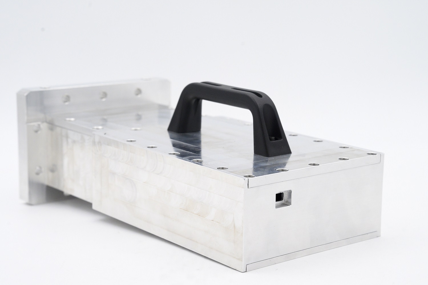
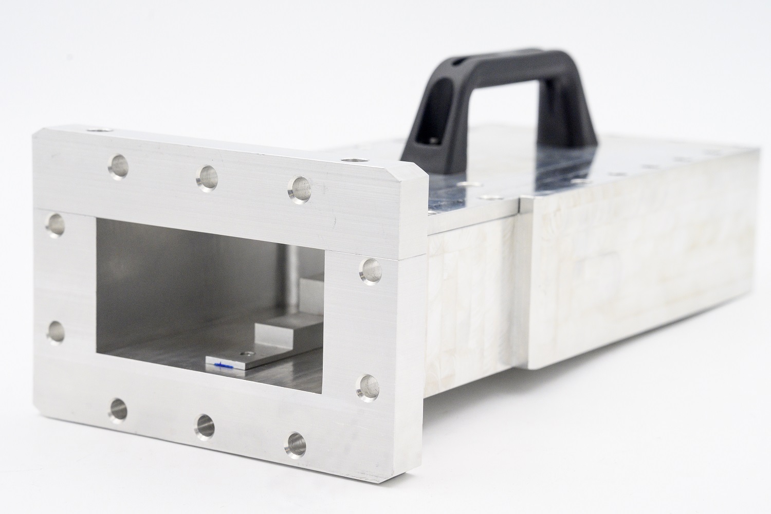
Figure 1. Picture of waveguide low power Vector Reflectometer around 2.45 GHz.
Operation Principle
The microwave source is implemented as a closed-loop PLL microwave synthesizer. The receiver is composed of two AD8302 integrated RF detectors. Due to the dual matched logarithmic amplifiers with a phase detector in the IC, the receiver offers a dynamic range of 45 dB and high stability across temperatures from -25ºC to 50ºC, covering low frequencies up to 2.7 GHz.
Separation of forward and reverse waves is achieved using two directional couplers to enhance directivity. Output voltage signals from the detectors are digitized by a multichannel analog-to-digital converter and processed by a microprocessor. This microprocessor is connected via a serial link to a personal computer or PLC controller. Digital control lines for the synthesizer are also managed by the microprocessor, synchronizing the entire measurement procedure.
Figure 2 shows the block diagram of the Low Power Waveguide Reflectometer, developed for off-line impedance measurements in industrial environments.
Calibration or adjustments with reference loads are not necessary, enabling non-experienced users in high-frequency measurements to tune or adjust microwave applicators
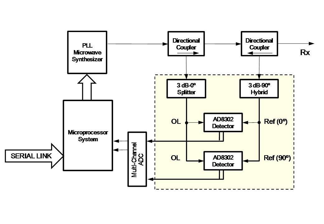
Figure 2. Schematic block diagram of the Low Power Waveguide Reflectometer
Control Software
The Vector Reflectometer is controlled via a PC or PLC controller connected through a USB, RS-232, or CAN serial link. For PC interfaces, a LabVIEW-based software has been developed, providing a user-friendly interface compatible with Windows 10 and XP.
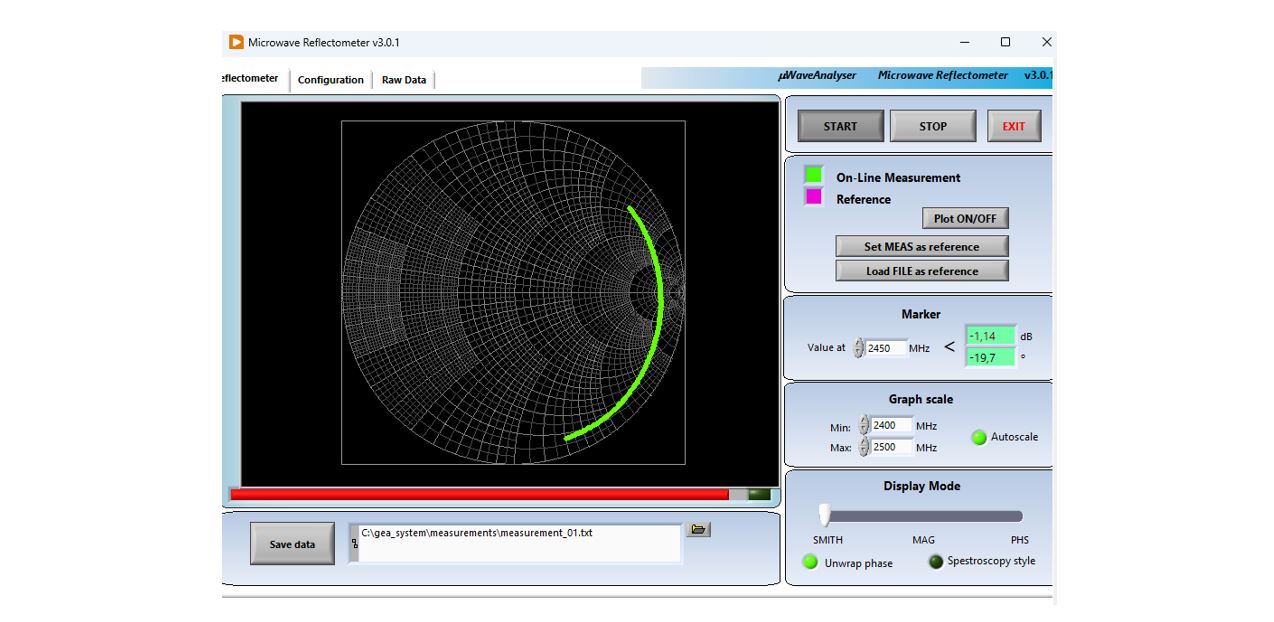
The control software allows for the automatic measurement of the magnitude and phase of reflection and impedance. Representation modes include logarithmic magnitude, phase (degrees), and Smith Chart.